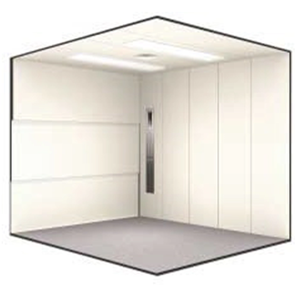
The xTreme-Lift
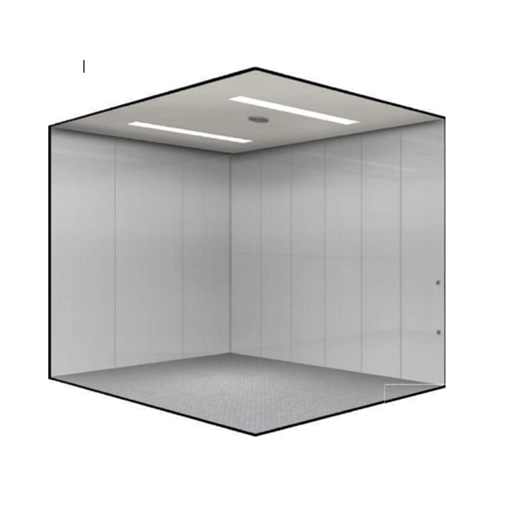
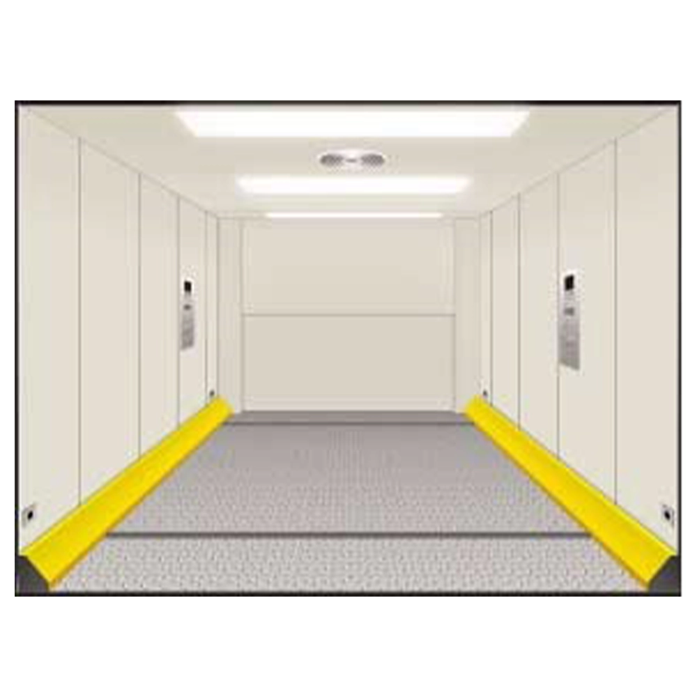
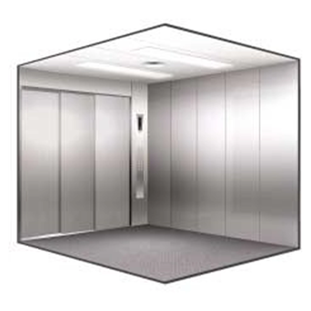
The xTreme-Lift is available in virtually all freely selectable cabin layouts from 3,000 mm cabin depth, from 6,500 kg load capacity and at speeds from 0.5 m/s to 1.6 m/s. Depending on the load capacity, speed and cabin equipment, shaft pits can be reduced to 1,200 mm and shaft heads minimised to 3,800 mm.
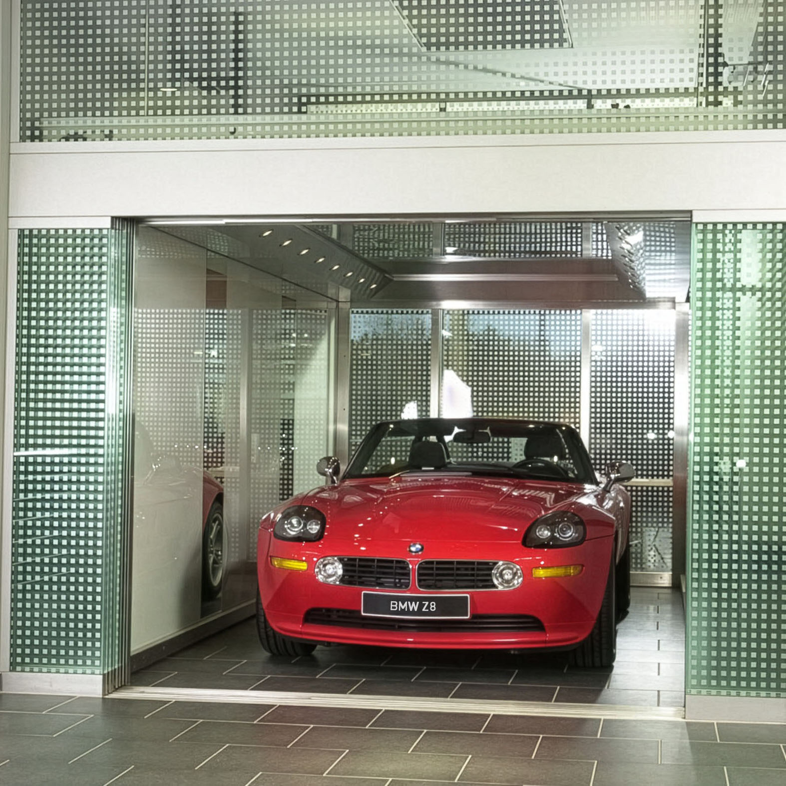
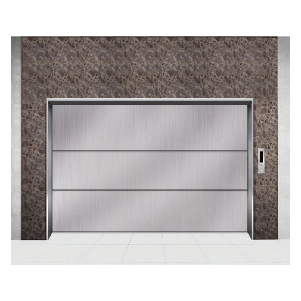
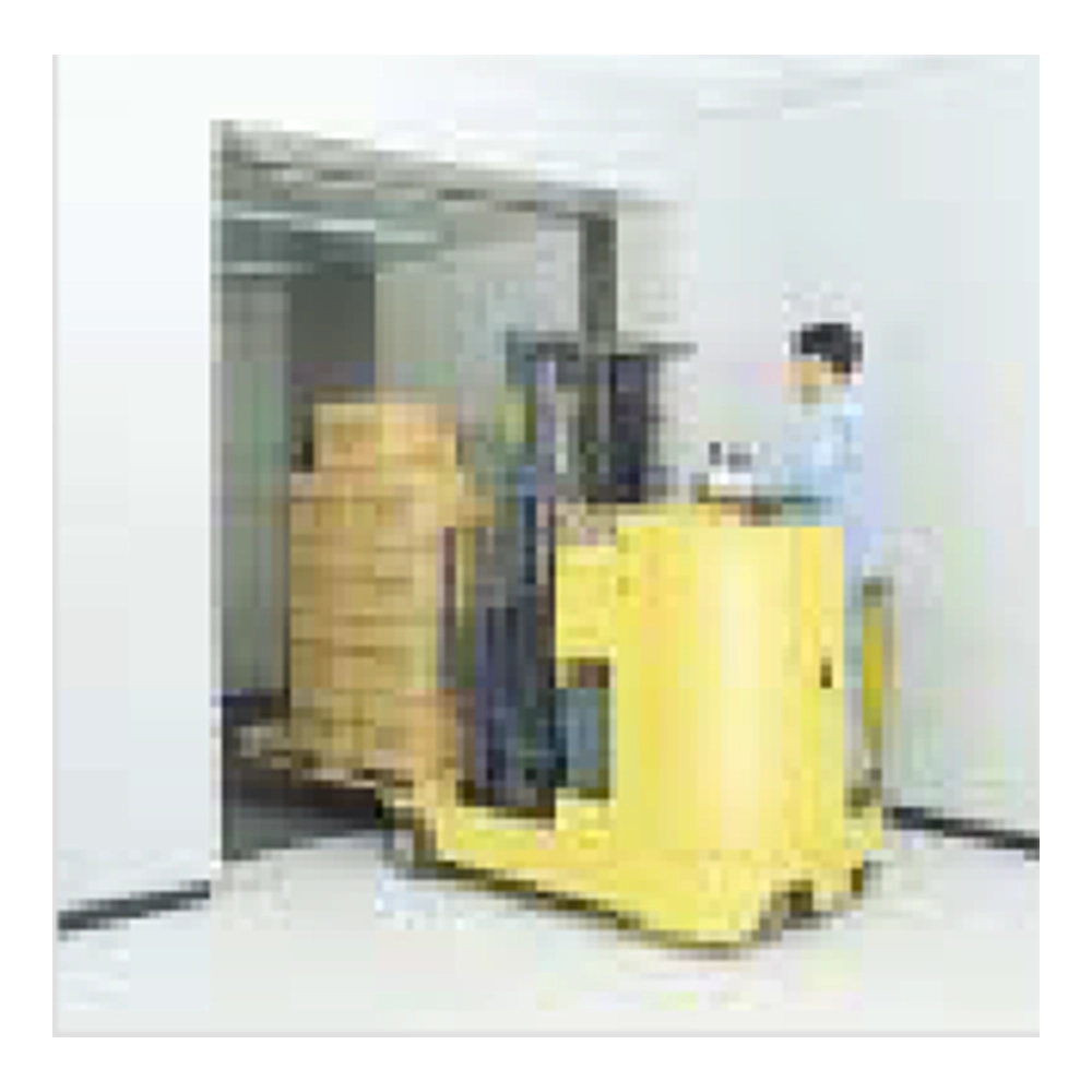
Freight lifts have all the general and safety features of conventional lifts for passenger transport. Freight lifts are primarily used in industrial and commercial enterprises, office buildings and multi-storey residential buildings for transporting production goods, furniture, motor vehicles, etc. While our conventional goods lifts – the xLift series – are also available in standard sizes, xTreme lifts are built exclusively for the individual requirements of heavy-duty goods transport and special logistics requirements. Freight lifts can be supplied with their own shaft or installed in existing building structures. KOHLER also builds and supplies xTreme lifts in a glass version as an option.
Freight lifts from KOHLER: For the toughest requirements.